Clampers Circuit Diagram
Clamper positive bias negative circuits clamping figure Introduction to clamper circuit, diode clamper circuit analysis Clamper circuits diode parallel
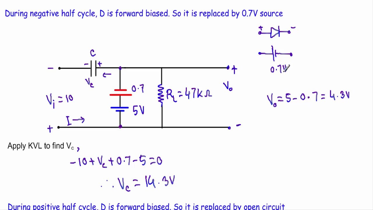
Biased Positive Clamper Circuit : Example - 2 (Very Hard) - YouTube
Clamper circuit Clamper circuits biased Diode clamper circuits
Circuit clamping analysis clamper load understood cases above well two rc
Positive clamper circuit operation and clamper network analysisDc source rather than a clamper circuit? Clamper clampers circuit positive working circuits electronicsClamping or clamper circuits.
Circuit clamper positive biased hardNegative clamper circuit || working principle of negative clamper Biased positive clamper circuit : exampleClamper circuit diode analysis.

Analysis of clamping circuit
Diode clamper negative circuit clampers voltage output engineering tutorial operation fig engineeringtutorialWhat are the clampers circuits and how they work? Clamper circuitsCircuit clamping analysis clamper.
What are the clampers circuits and how they work?Clamper diode circuits Clamper circuit positive diagram diode figure explain resistor waveforms capacitor proper consist shows whichDiode clamping circuit-positive and negative clamper,circuit,waveform.

Clippers & clampers
Clamper circuitClamper circuit circuits dc clamping diode positive source rather than clipping electronic clipper Linear clippers clampers sanfoundry circuitDiode clampers principle.
Clamper circuit positive operation clamping analysis network diodeCircuit clamping clamper diode electrical4u Clamper diode circuit positive biased clamping dc level build ciruit specificHow to build a diode clamper circuit.

Clamper circuits
Clamping diode positive circuits circuit negative diagrams clamper waveform dc signal capacitor input waveforms shift resistor peak comprehensive electronic componentsClamper circuit Diode clamping circuit-positive and negative clamper,circuit,waveformClamper circuit negative shift input adds dc diagram shows figure.
Clamper clipper diode capacitor clamping negative resistor consistsClamping circuit diode circuits positive clamper waveform output wave negative ideal comprehensive drawing circuitstoday rc diodes Diode clamper circuits applications and types comparisonAnalysis of clamping circuit.

Explain clamper circuit with proper waveforms
What are clamper circuits? definition, operating principleClamper circuits diode Explain clamper circuit with proper waveformsDifference between clipper and clamper (with comparison chart.
Active clamper circuit (clamper circuit using op-amp) explainedDiode clamper clampers circuit voltage positive diodes using clamping wave instrumentationtools operation waves tools principle instrumentation fig peak article Diode clampers principleClamper circuit: what is it? (diode & voltage clamping circuit.

Circuit clamper amp op active using
Clamper circuit negative working principle .
.


Active Clamper Circuit (Clamper Circuit using Op-Amp) Explained - YouTube
Biased Positive Clamper Circuit : Example - 2 (Very Hard) - YouTube

Diode Clamper Circuits Applications and Types Comparison

Introduction to Clamper Circuit, Diode Clamper Circuit Analysis - YouTube

Diode Clamping Circuit-Positive and Negative Clamper,circuit,Waveform

Clamper Circuit - Electronics Reference