Circuit Diagram To Verilog Code
Verilog unsuccessful converting compile Verilog code for full subtractor using dataflow modeling Subtractor verilog dataflow logic adder equations circuitikz follows technobyte
Solved a) Write a Verilog module for the circuit below using | Chegg.com
Verilog code microcontroller cpu control implementation unit diagram architecture alu block coding part memory project programming using shown implemented program Verilog code following xor circuit nor logic inverter not draw nand diagram gates assign input chegg transcribed text show output Verilog code for microcontroller (part 3- verilog code)
Mux multiplexer logic verilog 2x1 circuit
Verilog code shift register bit lfsr figure represents linear feedback solved draw p5 type input random reg circuit module numberSolved 5.28 the verilog code in figure p5.9 represents a Verilog circuit module code write below style using file structural separate turn create transcribed text show xyVerilog code for 2:1 multiplexer (mux).
Solved 6. for the following verilog code, draw theVerilog reset dff synthesis module circuit schematic sync modules Solved a) write a verilog module for the circuit below usingVerilog module.

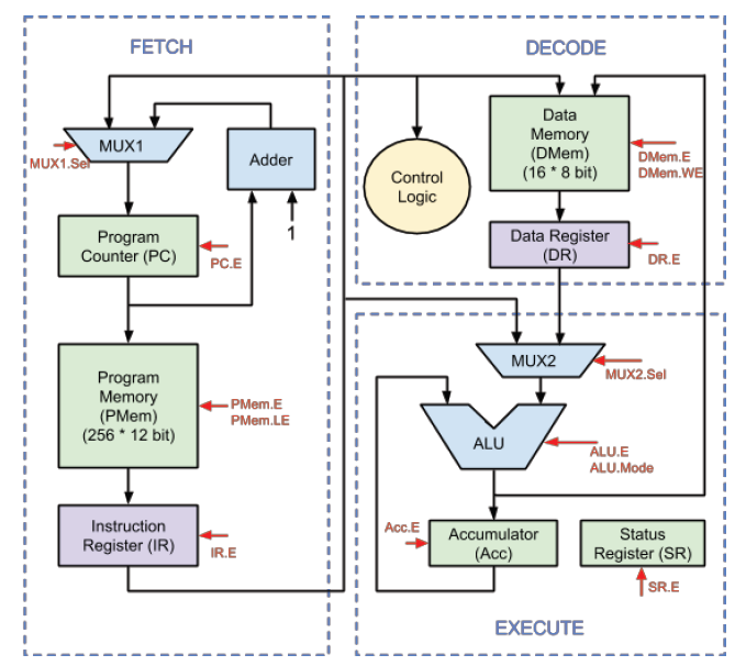
Verilog code for Microcontroller (Part 3- Verilog code) - FPGA4student.com

Verilog module

Verilog code for 2:1 Multiplexer (MUX) - All modeling styles

Verilog Code for Full Subtractor using Dataflow Modeling

Solved 5.28 The Verilog code in Figure P5.9 represents a | Chegg.com

sequential - Converting this schematic to verilog code, compile

Solved 6. For the following Verilog code, draw the | Chegg.com